2 pts Consider a waveguide with a circular cross-section. Cutoff Frequency equation for circular waveguide fc is defined below fc 18412 c 2pia Where c is the speed of light within waveguide and a is the radius of the circular cross section.

How To Use Circular Ports In The Rf Module Comsol Blog
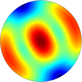
Waveguide modes exist that are characteristic of a particular waveguide structure.
. The cutoff frequency of TE 11 mode in this waveguide is 0879 GHz. This quantity is often but not always real valued. Subject - Microwave EngineeringVideo Name - TE Modes in Circular WaveguidesChapter - Microwave Transmission with Circular WaveguideFaculty - Prof.
In the window of defining waveguide port change mode number to 3 in order to find 3 initial modes of circular waveguide. It looks as shown in fig3. A circular waveguide of radius a.
It looks as shown in fig3. Cutoff Frequency equation for circular waveguide fc is defined below. Figure depicts Circular waveguide.
Acces PDF Circular Waveguide Tutorial mode conversion compared to non-asymmetric circular waveguide modes. Online Library Circular Waveguide Tutorial Based on the Generalized Multipole Technique GMT the Multiple Multipole Program MMP includes a large number of analytic solutions of Maxwell equations and because it is implemented in a flexible way future developments and adaptations can be made easily. For a circular waveguide of radius a Fig.
Cutoff Frequency equation for circular waveguide fc is defined below fc 18412 c 2pia Where c is the speed of light within waveguide and a is the radius of the circular cross section. The model of such waveguide cirQWpro can be loaded in QW-Modeller. It looks as shown in fig3.
Circular Waveguide Tutorial For dominant mode TE10 m1 n0 and hence λ c 2broad dimension 2a Circular waveguide. Mode TE 11 In this part the distribution of transverse and longitudinal fields components of TE. 2 pts Use variable separation of show that the solutions can be written as ψ ρ ϕ R ρ Y ϕ.
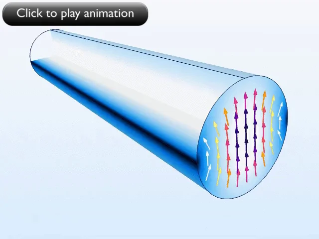
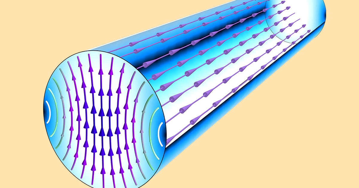
Circular Waveguide Tutorial For dominant mode TE10 m1 n0 and hence λ c 2broad dimension 2a Circular waveguide. A waveguide mode is a transverse field pattern whose amplitude and polarization profiles remain constant along the longitudinal z coordinate. The basic building block for all low-loss circulators and isolators is a nonreciprocal element with a phase shift dependent on the propagation.
The different particleThe circular waveguide with radius of 10 cm and the length of 30 cm is considered. Cutoff Frequency equation for circular waveguide fc is defined below fc 18412 c 2pia Where c is the speed of light. Cutoff Frequency equation for circular waveguide fc is defined below fc 18412 c 2pia Where c is the speed of light within waveguide and a is the radius of the circular cross section.
Unfortunately no current designs exist for circulators using the circular TE01 mode. Building the Waveguide Instead the mouse shortcuts are much better solutions and will save you lots of time Scroll-Wheel Zoom InOut Ctrl Shift Left-Click Drag Pan View Middle-Click Drag Scroll-Click Drag Rotate View Building the Waveguide Now that the design view is manageable we can move onto constructing the rest of the waveguide. M where p mn is Related Pages on RF Cafe Properties of Modes in a Rectangular Waveguide Properties of Modes in a Circular Waveguide Waveguide Flange Selection Guide.
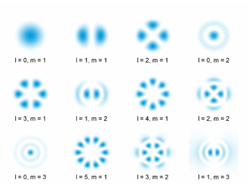
Modes are recognised in case of circular waveguides. Write the eigenvalue equation in cylindrical coordinates. Dominant mode in rectangular waveguide is TE10 and in circular waveguide is TE11.
Circular Waveguide - openEMS Circular Waveguide Tutorial For dominant mode TE10 m1 n0 and hence. In such situations the real and imaginary parts have separate interpretations. 24 Circular Waveguide x y a Figure 25.
The waveguide is excited at 1 GHz and its length is around half of a. Cutoff frequencies in a round waveguide in sequential order for the first TE and TM modes normalized to first TE 11 cutoff frequency-1st cutoff is dipole mode TE 11 x 11 184118-2nd cutoff is monopole mode TM 01 x 01 240483-Degeneracy differing modes but same cutoff frequency occurs when x 1n x 0n 1TM á 0TE á bandwidth 𝑀 1. Circular Waveguide Tutorial For dominant mode TE10 m1 n0 and hence λ c 2broad dimension 2a Circular waveguide.
It looks as shown in fig3. If the analysis involves some lossy part such as a nonzero conductivity or an open boundary the eigenvalue is complex. 2 pts Show that Y ϕ e i m ϕ and explain why m must be integer.
TM Transverse Magnetic Mode The lower cutoff frequency or wavelength for a particular TM mode in circular waveguide is determined by the following equation. Therefore the electric and magnetic fields of a mode can be written in the following form. 25 we can perform the same sequence of steps in cylindrical coordinates as we did in rectangular coordinates to find the transverse field components in terms of the longitudinal ie.
The waveguide mode in circular waveguide is described with m and n indexes which stand for the field variation in radial and axial directions respectively. In case of circular waveguides the fundamental mode is TE 11. In this video we will learn how to perform the mode analysis.
In mode analysis it is usually the primary goal to find a propagation constant. So run the simulation time domain it takes some minutes after that right click on port 1 in ports section at navigation tree at the left side of your screen and select object information and set frequency to 13 GHz then calculate the modes. C 2broad dimension 2a Circular waveguide.
You can find the number of modes that can be propagated with the lowest attenuation in any typ.
2

Circular Waveguide Field Youtube
Lossy Circular Waveguide
How To Use Circular Ports In The Rf Module Comsol Blog

Te And Tm Mode Patterns In A Metallic Circular Waveguide Youtube
Waveguide Modes

4 7 Circular Waveguide Rf And Microwave Engineering Fundamentals Of Wireless Communications Book
How To Use Circular Ports In The Rf Module Comsol Blog
0 comments
Post a Comment